LEDs play essential support roles in a wide range of devices across markets. They offer high efficiency, excellent reliability, and long lifetimes. Available in widths ranging from millimeters to microns, these light sources free OEMs to realize any form factor they can imagine. The LED needs to be specified to match the requirements of the application, however. Here are a few details to keep in mind as you review data sheets.
What are the details of your power supply?
Are you working off DC power or AC power? What are your voltage levels? Your LED will need to be compatible. Be sure to include appropriate circuitry to provide the forward voltage and forward current specified on the datasheet (more on this later).
What color/waveband do you need?
LEDs are direct bandgap devices that spontaneously generate photons when forward biased. The output wavelength – or, actually, waveband, because they are broadband emitters – depends on the bandgap of the material system. The modern LED market offers devices that operate at colors across the visible spectrum, as well as in the infrared and ultraviolet spectral regions (see table). In addition, white-light LEDs based on color mixing are available with a range of color temperatures.
For applications like indication, multicolor LEDs emit different colors depending on how they’re driven, enabling the same device to communicate changes in status to the user. In addition, RGB triads with controllers can be programmed to generate output colors that span the full color gamut and change in real time.
| Color | Wavelength [nm] | Semiconductor material |
| Infrared | λ > 760 | Gallium arsenide (GaAs)
Aluminum gallium arsenide (AlGaAs) |
| Red | 610 < λ < 760 | Aluminum gallium arsenide (AlGaAs)
Aluminum gallium indium phosphide (AlGaInP) Gallium arsenide phosphide (GaAsP) Gallium(III) phosphide (GaP) |
| Orange | 590 < λ < 610 | Aluminum gallium indium phosphide (AlGaInP)
Gallium arsenide phosphide (GaAsP) |
| Yellow | 570 < λ < 590 | Gallium arsenide phosphide (GaAsP)
Aluminum gallium indium phosphide (AlGaInP) Gallium(III) phosphide (GaP) |
| Green | 500 < λ < 570 | Traditional green:
Gallium(III) phosphide (GaP) Aluminum gallium indium phosphide (AlGaInP) Aluminum gallium phosphide (AlGaP) Pure green: Indium gallium nitride (InGaN) / Gallium(III) nitride (GaN) |
| Blue | 450 < λ < 500 | Zinc selenide (ZnSe)
Zinc selenide (ZnSe) Indium gallium nitride (InGaN) Synthetic sapphire, Silicon carbide (SiC) as substrate with or without epitaxy, Silicon (Si) as substrate—under development (epitaxy on silicon is hard to control) |
| Violet | 400 < λ < 450 | Indium gallium nitride (InGaN) |
| Ultraviolet | λ < 400 | Indium gallium nitride (InGaN) (385-400 nm)
Diamond (235 nm) Boron nitride (215 nm) Aluminum nitride (AlN) (210 nm) Aluminum gallium nitride (AlGaN) Aluminum gallium indium nitride (AlGaInN)—down to 210 nm |
Table: LED Materials and Output Colors
How much luminous intensity does the application require?
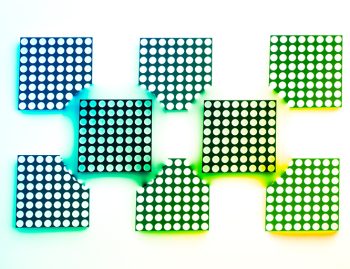
LEDs are efficient sources but individual devices are only capable of limited output. For an indication application, a single LED might be quite enough to provide sufficient luminous intensity. Functional illumination applications such as backlighting an overlay or logo may require an array of LEDs. Multiplying the number of LEDs doesn’t necessarily mean multiplying the amount of work – pre-integrated devices are available to streamline design and speed assembly.
What output distribution do you need?
The emission properties of LEDs mean that the light exits the chip throughout a range of angles. The output distribution varies depending upon the packaging of the chip, including whether it incorporates a lens. It’s essential to match the output distribution to the needs of the application.
If an LED used for indication needs a broad viewing angle, consider a flat lens (see figure 1). Adding diffusing material to the case helps eliminate hotspots, making it suitable for backlighting.

Figure 1: The output of a flat-face surface-mount device (SMD) LED (the Bivar SM0807) shows near-Lambertian emission (left). Incorporating a diffusing material to the epoxy resin case of a through-hole device results in a more homogeneous distribution (the Bivar R3YDL). (Source: Bivar)
Adding a lens to the packaging of an LED can be used to alter the distribution. A parabolic lens, for example, creates a more forward-directed output suitable for use with a light pipe, while a hemispherical lens provides a broader distribution (see Figure 2).
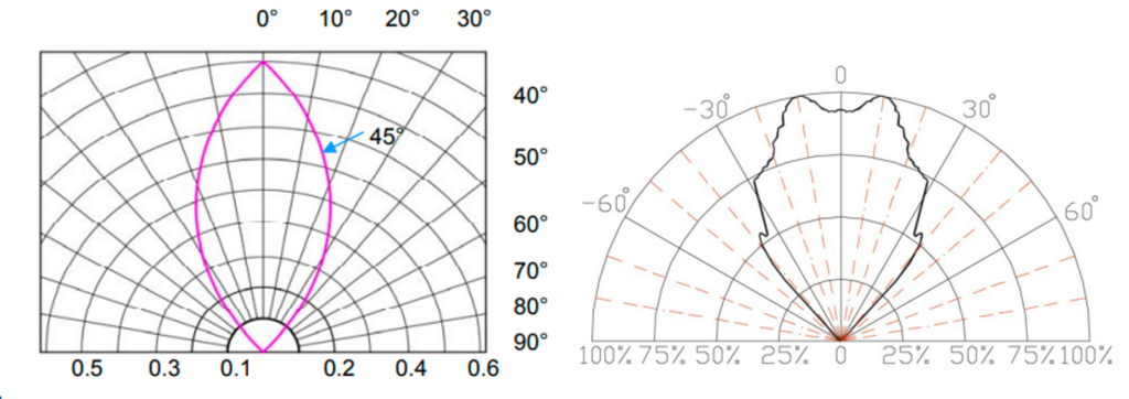
Figure 2: The parabolic lens of this through-hole LED (the Bivar 3BC-X) results in highly forward-directed output, while a hemispherical lens provides broader output (the Bivar R20BLU-5-0080).
Does the application involve high shock and vibration?
As solid-state devices, LEDs are highly robust – as long as they maintain their electrical contacts. There are three LED mounting styles, each of which offers different levels of tolerance for shock and vibration.
 SMD LEDs: SMD LEDs feature smooth bottoms with projecting leads that are soldered to contact pads on the surface of the board. They are compatible with fully automated assembly using pick and place and reflow soldering but have only moderate resistance to shock and vibration.
- Through-hole LEDs: With through-hole LEDs, the leads are threaded through predrilled holes in the printed circuit board (PCB), bent at 90°, and soldered in place. The mechanical connection adds to the strength of the bond. On the downside, assembly involves multiple steps, only some of which can be automated.
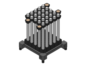
- Screw-mounted LEDs: For the toughest environments, a through-hole LED can be placed in a threaded bezel that is screwed into the PCB. The mount is not only shock and vibration resistant but very effective at heat dissipation.
How congested is your board layout?
LEDs require support circuitry. Current-limiting resistors protect against over driving a device to burn out. In addition, multicolor LEDs or those based on color mixing with RGB triads require controllers to manage output color. For projects with limited board real estate, look for devices with integrated resistors and controllers.
There are other options for addressing board congestion. As previously mentioned, multichip devices are designed to maximize output and manage heat while minimizing footprint. If board space is available, just not near the point of use, a light pipe can provide a very effective tool to bridge the gap.
Conclusion
When selecting an LED, the datasheet is not enough. Be sure to take into account the practical points discussed above. Take advantage of the expertise of your vendor – at Bivar, our sales and applications engineers have an encyclopedic knowledge of our products and what works best with any given product. Finally, don’t select your LED without first considering the light pipe you intend to pair with it – advance planning can lead to the best possible design.